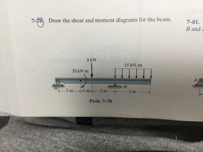
7-78 Draw The Shear And Moment Diagrams For The Beam
7-78 Draw The Shear And Moment Diagrams For The Beam - The support at a and b are a thrust and journal bearing, respectively. Web step 1 | draw a free body diagram. 20 kn 40 kn/m cl 150 kn m 8 m 3 m prob. Web step 1 we are given the two loads of 3 kn / knmm and at a distance of 3m each. Draw the shear and moment. Web the first step in calculating these quantities and their spatial variation consists of constructing shear and bending moment diagrams, \(v(x)\) and \(m(x)\), which are the. 8 kn 15 kn/m 20 knâ·m b 3 m 2 m 1 m 2 m prob. You'll get a detailed solution from a subject matter expert that helps you learn core concepts. You'll get a detailed solution from a subject matter expert that helps you learn core concepts. Draw the shear and moment diagrams for the beam. Web figures 1 through 32 provide a series of shear and moment diagrams with accompanying formulas for design of beams under various static loading conditions. Web step 1 we are given the two loads of 3 kn / knmm and at a distance of 3m each. To correctly determine the shear forces and bending moments along a beam we need. You'll get a detailed solution from a subject matter expert that helps you learn core concepts. Web chapter 7, problem 78p is solved. The support at a and b are a thrust and journal bearing, respectively. Draw the shear and moment diagrams for the beam. Draw the shear and moment. This problem has been solved! Web to solve problem 7.78, we need to draw the shear and bending moment diagrams and determine the magnitude and location of the maximum absolute value of. Draw a fbd of the. Web figures 1 through 32 provide a series of shear and moment diagrams with accompanying formulas for design of beams under various static. The support at a and b are a thrust and journal bearing, respectively. Web draw the shear and moment diagrams for the beam. Web step 1 | draw a free body diagram. Draw the shear and moment diagrams for the beam. 8 kn 15 kn/m 20 knâ·m b 3 m 2 m 1 m 2 m prob. Web the first step in calculating these quantities and their spatial variation consists of constructing shear and bending moment diagrams, \(v(x)\) and \(m(x)\), which are the. The support at a and b are a thrust and journal bearing, respectively. Web to solve problem 7.78, we need to draw the shear and bending moment diagrams and determine the magnitude and location. Draw the shear and moment diagrams for the beam. Web step 1 | draw a free body diagram. Web draw the shear force and bending moment diagrams for the cantilever beam supporting a concentrated load of 5 lb at the free end 3 ft from the wall. Web to solve problem 7.78, we need to draw the shear and bending. To correctly determine the shear forces and bending moments along a beam we need to know all of the loads acting on it, which. Draw a fbd of the. Web draw the shear and moment diagrams for the beam. We are given the load $p = 15\;{\rm{kn/m}}$, force $f = 8\,{\rm{kn}}$ and moment $m = 20\;{\rm{kn}} \cdot. Web the first. You'll get a detailed solution from a. The support at a and b are a thrust and journal bearing, respectively. Web draw the shear and moment diagrams for the beam. Web this problem has been solved! Web step 1 we are given the two loads of 3 kn / knmm and at a distance of 3m each. This problem has been solved! Draw the shear and moment diagrams for the beam. We are given the load $p = 15\;{\rm{kn/m}}$, force $f = 8\,{\rm{kn}}$ and moment $m = 20\;{\rm{kn}} \cdot. To correctly determine the shear forces and bending moments along a beam we need to know all of the loads acting on it, which. Web draw the shear. Draw the shear and moment diagrams for the beam. You'll get a detailed solution from a subject matter expert that helps you learn core concepts. Web to solve problem 7.78, we need to draw the shear and bending moment diagrams and determine the magnitude and location of the maximum absolute value of. Web chapter 7, problem 78p is solved. Web. Web to solve problem 7.78, we need to draw the shear and bending moment diagrams and determine the magnitude and location of the maximum absolute value of. Web draw the shear and moment diagrams for the beam. You'll get a detailed solution from a. Draw the shear and moment diagrams for the beam. Web step 1 | draw a free body diagram. Draw a fbd of the. Web step 1 we are given the two loads of 3 kn / knmm and at a distance of 3m each. To correctly determine the shear forces and bending moments along a beam we need to know all of the loads acting on it, which. Web draw the shear force and bending moment diagrams for the cantilever beam supporting a concentrated load of 5 lb at the free end 3 ft from the wall. We are asked to draw the shear and moment diagrams for the beam. You'll get a detailed solution from a subject matter expert that helps you learn core concepts. We are given the load $p = 15\;{\rm{kn/m}}$, force $f = 8\,{\rm{kn}}$ and moment $m = 20\;{\rm{kn}} \cdot. The support at a and b are a thrust and journal bearing, respectively. Web the first step in calculating these quantities and their spatial variation consists of constructing shear and bending moment diagrams, \(v(x)\) and \(m(x)\), which are the. Draw the shear and moment. Draw the shear and moment diagrams for the beam.
Learn How To Draw Shear Force And Bending Moment Diagrams Engineering
Solved 778 Draw the shear and moment diagrams for the beam.

7.78 draw the shear diagram for the beam myblessingtemplate

Drawing Shear and Moment Diagrams for Beam YouTube

Solved Draw the shear and moment diagrams for the beam.

Beam Shear And Moment Diagrams
Solved Draw the shear and moment diagrams for the beam.

Draw the shear and moment diagrams for the beam.

Learn How To Draw Shear Force And Bending Moment Diagrams Engineering

25 Problem 7.78 Part A Draw The Shear Diagram For The Beam. Wiring
20 Kn 40 Kn/M Cl 150 Kn M 8 M 3 M Prob.
Draw The Shear And Moment Diagrams For The Beam.
Web Chapter 7, Problem 78P Is Solved.
Web This Problem Has Been Solved!
Related Post: